From
Patrick Kübler
May 26, 2026
15 minutes
Engineering

I. Three design engineers. Just to check drawings.
A few weeks ago, I visited one of our customers – a medium-sized German machine manufacturer. They build highly complex, custom machines in manageable annual volumes. They design in 3D but outsource a significant portion of component manufacturing. I was there to discuss typical engineering pain points: variant engineering, design-to-order, and search times. Instead, the engineering manager brought up an unexpected issue: drawing verification.
The process sounds simple at first. A design engineer derives 2D drawings from the 3D model, adding dimensions, tolerances, welding specs, materials, and standard references. Then comes the second step: another engineer reviews every drawing using the four-eyes principle. They check if everything is fully marked up, tolerance chains are plausible, and references to standards and internal company guidelines are correct.
The team spends about four working days per machine purely on drawing verification. Scaled to their annual production, this equals around 3 FTEs – three full-time design engineers doing nothing but double-checking. These three engineers are missing when it comes to designing new components, which directly increases product costs and delivery times. Furthermore, drawing verification is monotonous work where errors are easily overlooked. Ordering wrong parts based on faulty drawings is the inevitable result.
Is this an isolated case? In the following weeks, we specifically raised this topic in exploratory discussions with other machinery manufacturers – ranging from custom machine builders with fewer than 100 employees to component manufacturer with over a thousand. The result: Every single company we met struggled with this issue.
Industry research confirms this. The Steinbeis Consulting Center for Design estimates that more than half of all product specifications have significant, verifiable flaws regarding functional, manufacturing, inspection, and cost-optimized tolerancing. Meanwhile, a survey by engineering software provider CoLab shows that respondents would, on average, trust AI to handle 72 percent of their drawing reviews based on their own company standards.
II. Are 2D drawings history? Not in Industrial Engineering.
For years, the industry has talked about Model-Based Definition (MBD) and the digital thread, aiming to phase out 2D drawings. In industrial engineering practice, however, things look different, and this will only change gradually. This article explores why this is the case, the manual effort it causes daily, why legacy verification tools fail, and how to close the gap with the right approach.
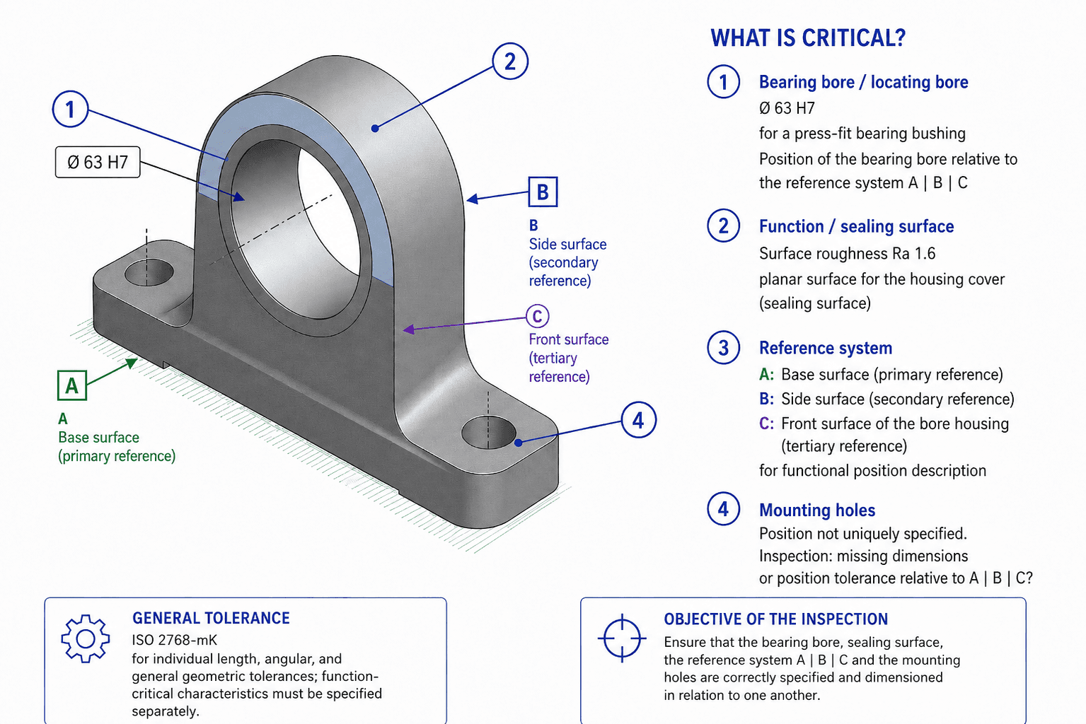
To make these abstract concepts tangible, I will refer back to a practical example: a bearing block. It features a critical Ø63 H7 bore for a pressed-in bearing bush, a datum system A|B|C, a static sealing surface for the bearing cover with Ra 1.6, and general tolerances according to ISO 2768-mK.
III. In theory, 2D drawings are obsolete.
Essentially, a 2D drawing is a translation document. You create the design in the 3D CAD system, and the drawing is the manual translation of this model into a format readable by manufacturing and legally binding for purchasing.
This translation should no longer be necessary. Since the early 2000s, standards have allowed engineers to store all manufacturing information directly in the 3D model as Product Manufacturing Information (PMI): ASME Y14.41 (2003), ISO 16792 (DIN ISO 16792 in Germany), and STEP AP242 as the exchange format between CAD, CAM, coordinate measuring machines (CMM), ERP, and suppliers.
Under the Model-Based Definition (MBD) framework, the 3D model becomes the single source of truth. Tolerance chains, datum systems, surface finishes, and welding callouts are not just labels on the model; they are explicitly linked to geometric features. This results in only one dataset instead of two. Data flows automatically from CAD to CAM to quality inspection software, and BOMs, routings/work plans, and inspection documents can be derived directly from the model using predefined rules.
In theory, the problem is solved – and aerospace and automotive industries have partially adopted this concept.
IV. The reality in Industrial Engineering is different.
During discussions with numerous machinery companies – including highly digitalized ones – an engineering manager made a statement that stuck with me: "Introducing PMIs in design engineering is something I have simply not been able to push through yet."
International studies match this sentiment. A survey of the Finnish machinery industry shows that while major companies are aware of PMI/MBD, fewer than half actually use it. A Tech-Clarity survey of MBD users shows high satisfaction (89 percent would make the shift again) but names implementation costs, legacy drawing databases, and a lack of organizational drive as the main adoption barriers.
V. Why the industry sticks to 2D drawings
A closer look reveals valid reasons for every role involved as to why PMI has not yet succeeded in machinery manufacturing.
The designer's view: Effort and mindset
In practice, storing PMI data directly in the 3D model means significantly more work during the modeling phase. Tolerances, datums, notes, and materials must be explicitly attached to geometric features, which requires spatial planning and semantically correct placement. Then there is the designer's mindset: when modeling, you focus on function, not production. Taking a production-oriented view once during 2D derivation is efficient; maintaining it throughout modeling slows down the design process. On a practical note, additional PMI data visibly degrades load times and visualization performance for complex assemblies, often requiring separate views.
Why automated 2D drawing derivation fails
The obvious step – automatically generating the 2D drawing from the 3D model in the CAD system – does not work reliably in practice, even with leading CAD suites. The reason lies deeper than tool maturity. A 2D drawing is not just a simplified view of the 3D model; it is a mental transfer process. The designer visualizes the production workflow, selects the exact cross-section needed for machining, dimensions only what is relevant to manufacturing, and adds tolerances where function or production demand them. An automatically generated drawing, on the other hand, contains either too much or too little information – making it useless for the shop floor.
The shop floor view: Speed beats elegance
Machining technicians want to see what matters for their specific step at a single glance. A clearly readable cross-section on paper or a local screen is unbeatable for this. In contrast, a 3D model with PMI requires skilled handling of a 3D viewer, MBD-compatible licenses at every workstation, rugged hardware in a harsh production environment, and a logic where users must toggle layers on and off to find relevant details. The main worry on the shop floor is that searching for information slows down operations, risking throughput times and delivery dates.
The purchasing and supplier view: Legal security beats digital thread
In B2B business, a technical drawing is a contract – the legally binding foundation between buyer and supplier that dictates complaints, warranty claims, and product liability. This is why many suppliers – especially medium-sized ones – continue to insist on 2D drawings. They serve as an unalterable document that can be clearly assigned to a purchase order, archived, signed, and presented in court. It is also a format suppliers can process without expensive PMI-enabled CAD systems. Until this legal function is transferred to the 3D model in a comparable way, the 2D drawing will remain part of every purchase order – even if internal processes are already PMI-capable.
Conclusion from the four perspectives
The 2D drawing will not disappear from industrial engineering anytime soon. The barriers to PMI are structural: design effort, the limits of automatic derivation, ergonomic and economic demands on the shop floor, and legal requirements in procurement. This does not mean MBD and PMI are not worth pursuing. Their adoption will grow over the coming years, but not overnight.
For many companies, the question today is not "How do we get rid of the 2D drawing?" but rather: "How do we automate the manual work associated with the 2D drawing?"
VI. Why legacy verification tools fail
Current tools for drawing verification fall into four categories. None of them solves the core problem.
1. CAD standard checkers
Every major 3D CAD suite includes its own standards checker. These check layer conventions, font sizes, line weights, consistent dimensioning styles, and mandatory title block fields. This is useful for maintaining style discipline, but it is a format check, not a content check. Ensuring if a dimension is logical and complete, if the tolerance chain closes, or if the ISO 2768 class matches the geometry is outside their capabilities. Even for the title block, the tool only checks if the fields contain text – not if the content makes sense for the drawing.
2. CAD validators for system data exchange
These tools originate from PLM data exchange. They verify that geometry, PMI, and dimensions have been transferred without loss when converting between CAD systems or file formats – such as comparing a native CAD dataset with its STEP AP242 counterpart. However, they are the wrong tool for checking a drawing against standards and internal rules. Here, there are no two datasets to compare; there is only one drawing, and you need to know if it is consistent and compliant in itself.
3. OCR and image-based extraction services
A third group rasterizes the drawing and uses OCR (often AI-supported in modern versions) to read text and values. This reliably extracts title blocks with fixed layouts (material, drawing number, revision, scale). A typical use case is bulk importing master data from supplier drawings into ERP systems. Beyond that, recognition rates drop, and a core question remains: Which design feature does a recognized dimension belong to? A tolerance callout is not just text; it is a complex construct of nominal dimension, deviations, tolerance frame, geometric tolerancing symbol, and datum. The system reads "Ø63 H7" but cannot tell you "this tolerance belongs to the bore in view B-B with datum C." Anyone wanting to check a drawing needs exactly this link: dimension ↔ feature ↔ position. Because of this, these services are mostly used for preprocessing, leaving the actual verification problem unsolved.
4. AI-based drawing checkers
The latest generation passes the drawing and ruleset to a large language model to generate findings. Checking speed is high, and the feature set is growing, but three weaknesses remain.
Reproducibility: The same drawing does not reliably produce the same findings, which is a blocker for quality-assured processes.
Traceability / localization: A finding like "tolerance chain not closed" without being deterministically anchored to specific drawing elements is difficult to verify or fix.
Internal standards and customer rules: A generic language model does not know the notation habits of a long-term customer or deviation rules from the DIN standard. It would need to be manually fed this data, leading back to the first two points.
What all four categories lack
Any tool that reliably automates drawing verification must meet four requirements:
Localization (each finding points to the exact graphical object, not "somewhere in the top left"),
Reproducibility (the same input always yields the exact same finding – otherwise, the tool is useless for QA-certified processes),
Traceability (every finding has a verifiable reasoning path that an experienced engineer can review), and
Integration of internal rules (factory-specific design and drawing guidelines must be checked alongside public standards).
Today's tools either lack these four properties entirely or fail to combine them systematically.
VII. How can we solve these limitations?
In my view, four components are essential to achieve this.
1. Native vector parsing instead of image recognition
Modern drawings are rarely stored as pixel images; they exist as vector formats – usually DXF from the CAD system or PDFs containing vector data. Lines, dimensions, text, tolerance frames, and section arrows are geometrically exact. A high-quality 2D analysis parses vector objects directly instead of rasterizing them and guessing on a pixel level. Image recognition remains the fallback for scanned legacy drawings, not the primary path.
2. Linking each annotation to its product feature
This is the key differentiator from classic OCR solutions, which output a pile of recognized values without linking them to a bore, surface, or datum. Instead, we generate a structured description of the component where every element carries a stable ID. For example, a fully specified bearing block drawing would yield: "Central bore Ø63 H7 in view B-B, positioned relative to datums A|B|C; static sealing surface to the right of the bore with Ra 1.6; general tolerance ISO 2768-mK in the title block." These IDs make findings localizable: a notification stating "The fit bore Ø63 H7 lacks a complete datum system" becomes a link that takes the designer directly to the correct spot in the drawing. This structure is source-independent – a bore remains a bore, whether parsed from a 2D drawing or extracted from a 3D model.
3. Deterministic core with targeted machine learning
Data extraction and rule checking must be deterministic. Questions like "Does this bore have a tolerance?" or "Is this tolerance frame placed on a datum surface?" are answered by code that delivers consistent results every time – not by an AI model. Machine learning is only used for targeted tasks, such as recognizing a poorly drafted tolerance frame or a difficult-to-read surface symbol. Predictions made by machine learning are cross-referenced with vector geometry; if they do not match, the system discards the prediction. Large language models are only used to formulate helpful explanations for findings, not for the evaluation itself. This ensures all statements remain reproducible and auditable.
4. Knowledge graphs for standards and internal guidelines
ISO and DIN standards are only half the story; internal plant guidelines are just as important. These include specific tolerance classes, surface finish rules for seals, welding symbols, and datum concepts. We store both in the same knowledge graph, clearly flagged as "public standard" or "internal rule." A verification rule becomes a path within this graph that you can easily write, modify, and audit. This brings immediate practical benefits: findings become specific ("missing tolerance on bore Ø10 at position A3" instead of "missing tolerance"). The tribal knowledge of senior designers is captured once and applied to all future checks. Updates to internal guidelines are clearly documented for audits and warranty claims.
The 3D bridge is mandatory
The same architecture that breaks down 2D drawings into typed features can decompose 3D models using STEP data – identifying bores, pockets, slots, and threads with their position, geometry, and relationships. This allows us to automate three processes that today only happen via spot checks: consistency checks between drawing and model (do all dimensioned features exist in the model? do the main dimensions match?); similarity searches across the entire database, even where parts only exist as drawings (some customers have 25% of their database in this format); and a continuous digital link from the tolerance frame in the drawing to the 3D model feature and the standard in the knowledge graph because all elements share the same IDs.
VIII. What can we verify and automate – and what is out of scope?
What we can reliably verify today
Provided the drawing quality is sufficient and the rules are formalized, the following tasks can be automated effectively:
Geometric tolerances on functional surfaces, including valid datum systems and surface finishes on sealing, fitting, and functional surfaces
Dimension completeness and clarity (position, diameter, no redundant or missing datum dimensions) and correctly referenced general tolerances (ISO 2768, DIN standards, or company classes)
Welding symbols and title block compliance, including material, semi-finished products, surface treatment, standard references, and tolerance class
Drawing-to-model consistency and compliance with formal drawing standards (layers, line weights, dimensioning style) in a single run
Manufacturing and material-specific rules from standard or factory guidelines – such as minimum bend radius according to DIN 6935 for a given sheet metal thickness and material combination
For example, running a check on an incomplete bearing block drawing would report: "Fit bore Ø63 H7 found, but datum C is missing in the datum system"; "Sealing surface detected but lacks surface finish value"; "General tolerance defined in title block but contains no exception for the functional dimension." Providing these specific, localized findings – showing the exact gap between target and actual – saves significant review time.
What cannot be automated
A 2D analysis cannot replace engineering judgment. The following tasks cannot be automated:
Evaluating if a design makes mechanical sense (force flow, leverage ratios, component strength under operating loads) and strength or stability checks, which belong in the FEM domain and require loads, boundary conditions, and material models
Selecting the manufacturing concept (weldment vs. casting, machined vs. sheet metal, single vs. multi-part) regarding function, cost, and lifecycle
The functional strategy behind dimensioning: whether the selected datum surfaces are practical for metrology and if tolerance chains remain manageable on the shop floor. For our bearing block, the system can verify that a datum path is complete; however, whether these specific datums make the most sense for production is an engineering decision.
What automations you can implement with this approach
Once the drawing is available as a structured, verifiable data source, it enables four concrete use cases.
Drawing verification is the most direct application. Every drawing – created internally or sent by a supplier – is checked against standards and company specifications before release. Findings are returned with exact locations, allowing the designer to fix errors immediately.
Reusability over new parts creation: Before releasing a new part and creating master data, the system runs a similarity search across the database using feature vectors from 3D models and 2D drawings. This closes a gap that standard solutions cannot resolve – especially in legacy databases where many parts only exist as drawings.
Work plan / routing recommendations: By matching typed features and tolerances with legacy data on machinery, operations, and setups, you can generate initial routings. For example: "For a turned part with this geometry and IT7 tolerance, machine X with setup Y was used in 80% of cases." Work planners can review and adjust instead of starting from scratch.
Pre-filled quality inspection plans: The system can extract critical dimensions and tolerances from the drawing to draft an inspection plan, suggesting which dimensions to measure, how often, and with which method. Quality management simply approves it instead of starting from a blank page.
This frees up time for core engineering design instead of repetitive checking tasks – even if your team does not use PMIs yet.
What we are building at wailand
We recognize the 2D drawing as a critical link between engineering and manufacturing and build software to solve these exact friction points.
Onboarding typically follows three simple steps:
Step 1 – Recognition test with 10 drawings
You upload ten typical drawings from your database. We run them through our system to show you what was correctly recognized, what was flagged as unclear, and where the system reported "cannot be decided." Timeline: minutes to a few hours.
Step 2 – Integration of standards and internal rules
We import your internal design and drawing guidelines into the knowledge graph and connect them with public standards. Any open points are resolved quickly with an experienced designer from your team. We run your ten drawings again, this time against your complete profile. Timeline: hours.
Step 3 – Optional IT integration
If you want to automate checks within your CAD release workflow or incoming quality control, we utilize pre-built connectors on our integration platform. For custom ERP or PLM systems with legacy modifications, we set up tailored connections in a few hours to days.
You see the value before committing to any IT integration. After Step 1, you know if the recognition is accurate. After Step 2, you see how well your internal guidelines are represented. All of this is set up in days, not weeks or months – avoiding the risks of typical custom software projects.